Like Terence McKenna once said, “The further you go the bigger it gets.” If you begin your own exploration of the world of modular synthesis you will learn that you have likely bitten off more than you want to chew. Case in point, tuning, and calibration. After upgrading firmware there is often a requirement that the module must be re-calibrated. This is typically done by sending a 1 volt and a 3 volt signal to the device that signifies particular notes such as C2 and C4.
On the other hand, there is my Ultra Random Analog (URA) from Steady State Fate which is a random voltage generator. While following a tutorial for it I just couldn’t get the same effect out of it in the same way, as what was being shown in the video. At the time it would have been easily explained that I simply wasn’t understanding much of what I was trying to learn. Over on Muffwiggler, I found a conversation about other units that weren’t calibrated correctly and it read like this was exactly my problem. I did the best I could but was very uncertain about what I was doing.
Fast forward some months and now armed with a better bit of knowledge I can tell that my URA is still not calibrated correctly. I first need to remove the module from the rig but leave it plugged in as it will need power to it in order for me to make the required adjustments. To do this I’m lucky enough to have an oscilloscope from Mordax called the DATA, it’s a great Eurorack module everyone should own. There are three things that require calibration on the URA a clock that sets a gating frequency and two noise sources that should fall between particular voltage levels. The clock for the gate is calibrated by listening and choosing a timing that works best for the owner of the module. The other two calibrations are a bit more involved.
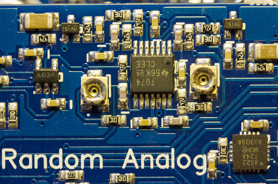
This is where the oscilloscope comes in. I have to send a particular signal out of the URA into the oscilloscope that is set to sample the incoming signal at 10ms and measure the voltage from +10 volt to -10 volt. From the first output, I need to adjust the left pot (the little round things) you see above on the sides of the chip. I have to be careful to not turn too far as these are fragile and easily damaged. I’m looking to set them so they are producing brief peaks of +10V and -10V on the oscilloscope. When I’m done with the first pot I move the cable to the other jack and start measuring its signal. Somehow I missed this part of calibration on the first pass those months ago, as the second channel is off by a mile. By the way, while the miniature screwdriver is touching the pot the signal is being skewed so you make a small adjustment and remove the screwdriver to get a clean measure and then go back to it again until you get the range tuned in.
Fortunately, this isn’t a common thing that has to be done on many modules, but having the tools and determination to get it done lets me know a little bit more about this complex hobby that has me feeling like a mad scientist from time to time. I think the writing is on the wall that somewhere in the not-too-distant future I’ll be soldering my own synths so when a module needs a simple repair I’ll have the confidence to do that too.